- HOME
- Solution
- OmegaLand Educator
- Heat Transfer Simulator


OmegaLand Educator Heat Transfer Simulator
Users can learn principles and rules of process engineering efficiently.Aim of Heat Transfer Simulator
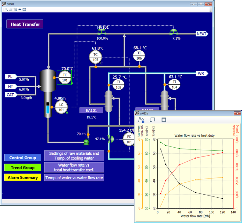
The purpose of this simulator is to learn about heat transfer which is a principle and basis of chemical engineering, through a process that removes heat from a polypropylene polymerization reaction by use of two external circulation coolers.
Using this simulator will enable:
- Understanding heat exchanger duties, the log mean temperature difference, and the overall heat transfer coefficient
- Understanding the relation between cooling water rates and the overall heat transfer coefficient
- Learning how to tune PID parameters by using the reactor temperature controller
Target Process
This a process to remove the polymerization reaction heat of polypropylene with two external circulation coolers. Here, the reactor is used simply as a heat source.
The two coolers have the same characteristics, but the cooling water flow rate of the first one (EA101) is controlled by the temperature of the reactor, while the other one (EA102) is not constrained by temperature control. Therefore, varying the cooling water flow rate to EA102 will cause the cooling water flow rate to EA101 to be controlled so as to maintain a constant reactor temperature.
Some of the process fluids exiting the coolers are recirculated to the reactor through a manually operated valve.
Exercise Contents
- Collect data with a constant cooling water flow rate through EA102, and find the heat exchange rates of the two coolers, their logarithmic mean temperature differences, and their overall heat transfer coefficients.
- Perform the temperature control of the reactor with EA101, change the water flow rate to EA102, and collect data related to the temperature around EA102 and the overall heat transfer coefficient. Plot the collected data as a graph, and consider the relationship between the logarithmic mean temperature difference, the overall heat transfer coefficient, and the heat exchange rate when changing the water flow rate.
- Set the flow to EA102 to zero, and create an environment in which the heat exchange rate is constant and the heat transfer area of EA101 is doubled. Then collect data of the cooling water flow rate to EA101, temperature, and overall heat transfer coefficient when changing the cooling water supply temperature. Plot the collected data as a graph, and consider the relationship between the water flow rate, the temperature difference, and the overall heat transfer coefficient when changing feed water temperature.
- HOME
- Solution
- OmegaLand Educator
- Heat Transfer Simulator
Copyright © Omega Simulation Co., LTD. All Rights Reserved.