- HOME
- Products
- Visual Modeler
- Overview


Overview
Dynamic process simulation already existed in the 1960s, and a substantial number of general-purpose dynamic simulators were developed during the period; some of them were sold for business purposes. It was not, however, until recently that the dynamic simulator made significant improvements in its usage and functions. Today’s operation training simulators are very different from conventional ones in that they are upgraded to a level where highly skilled operators can effectively utilize them, and their ability to construct first-principle-based rigorous models enables safe and efficient operations with a smaller number of people; the conventional ones, however, are merely used as a supplementary means to educate non-skilled operators due to lack of fidelity in the models. While the dynamic simulator is generally used to advance operating and control systems for analytical purposes, today’s simulator is required to be more accurate to create optimal operation characteristics through online simulation. From a user’s standpoint, plant operations have become much harder since the necessity of maintaining safe operations and reducing the number of shutdowns and startups of the plant is becoming greater as plants become more complex. From a provider’s stand point, on the other hand, it has become much easier to develop better-quality simulators because of the advancement of graphic user interfaces and computer calculation methods.
Visual Modeler, a dynamic simulator, proudly presented by OSC, was developed to meet those users’ needs with the goal of not only providing operation training, and developing and inspecting advanced operating control systems, but also offering a next-generation plant simulator as a commonly used tool to achieve optimal operations in online systems.
FUNCTIONS REQUIRED FOR DYNAMIC SIMULATORS
Since the steady-state simulator is more commonly used, its functions are standardized, whereas the functions of the dynamic simulator are very diverse; therefore, no standardized reference is available. The following describes the features of functions in Visual Modeler providing similar and different characteristics between the dynamic simulator and the steady-state simulator.
Model Fidelity
The unit models constructed in dynamic simulators (e.g. distillation tower, heat exchanger, etc.) require the same or higher level of accuracy than those in steady-state simulators. For example, the vapor-liquid equilibrium, and heat balance calculations are performed at each tray in the distillation column, and the internal pressure caused by changes in the vapor hold-ups is calculated. Both functions are done in the same manner in the dynamic and steady-state simulators. For the heat exchanger, while it is only necessary to show the heat and material balances of the inlet and outlet in the steady-state simulator, the dynamic simulator must have the ability to describe the inner conditions in detail because of its dynamic characteristics. The valves, which are often overlooked or only recognized as units that generate pressure differences in the steady-state simulator, must be modeled as units in the dynamic simulator with which flow rates, velocities (how fast valves are opened and closed) and other variables can be described.
The physical property calculation methods in the dynamic simulator are basically the same as those in the steady-state simulator. However, when it is necessary to execute at high speeds, the dynamic simulator can use simple calculation methods, such as quadratic equations with given temperature variables. Visual Modeler can offer high accuracy and calculation efficiency because of its capability of using any combination of the calculation methods simultaneously in one model.
Scale of Simulation
To examine the training and operations in dynamic circumstances such as shutdown and startup, dynamic simulators require modeling of control equipment, pipe lines, hand valves, and safety and auxiliary equipment. Thus, for the same type of plant, they require 10 to 100 times more units than steady-state simulators. Some large-scale plant simulators consist of several thousand units (including measurement and control units). Visual Modeler can handle process models with 10,000 - 20,000 units.
Standard Unit Modules
Units required in the dynamic simulator but not in the steady-state simulator include tanks, safety valves, check valves, time lag pipes, measuring instruments and control equipment. While the same results can be obtained from one unit model in the steady-state simulator, the dynamic simulator often requires each unit model to function identically to the actual one because of its dynamic characteristics and different handling procedures in operations (e.g., pumps, compressors, valves of every kind, filters in the pipes and other small equipment). For this reason, many different types of unit models must be prepared as standards in the dynamic simulator. Tables 3 and 4 show a list of standard unit models registered in the Visual Modeler library.
User Unit Modules
Although the dynamic simulator carries various types of standard unit models to meet different conditions, the cases where these models are insufficient occur more frequently in the dynamic simulator. The reasons are: 1) the size and shape of equipment and/or the heat capacity are required to be specified to show dynamic movements; thus the structural features are easily reflected as discrepancies in models; and 2) more variety of models are required to be designed for emergency situations and abnormal operations. It is, therefore, of utmost importance that there be functions which users can easily use to add unit models to the library at their discretion. Visual Modeler features effective functions to achieve this purpose, and as a vital tool for model descriptions, OSC offers software called EQUATRAN, an equation solver language.
Execution Functions
Simulation enables execution in real time and interactive responses per second. These are extremely important especially when training simulators are used as real-time systems. They also become very effective in situations where engineers use them for analytical purposes and want to feel a sense of realism. The interactive response means that users are able to verify responses every second on the screen after valves are manually opened and closed; longer intervals will not duplicate the sense of realism.
Visual Modeler uses a high-performance computer to calculate large-scale simulators with rigorous models on a per-second basis. And, it features unique functions to accelerate the calculations of each unit model, physical properties, and the pressure flow network balance of the entire plant.
Engineering Environment
When dealing with a large-scale plant, the development job becomes much easier if it is divided into groups. In Visual Modeler, one plant is divided into several process models, and the engineers assigned in each division perform development tests independently. After all the tests are completed, they are combined into an integrated plant model.
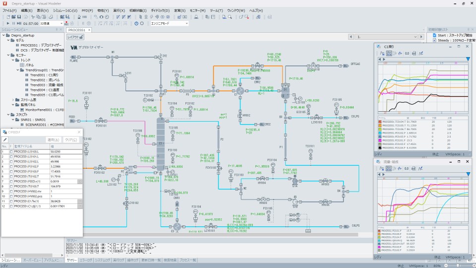
While the process flow diagrams (PFDs) are generally used to build models in the steady-state simulator, the dynamic simulator requires a more efficient operating environment with GUI due to the use of a substantial number of unit models. Models are created by 1) selecting necessary unit models from the Library menu, 2) placing them on the PFD, 3) connecting them with streams and signal cables, characteristic data) for each unit model. Figure 1 shows an example of the model-editing panel in Visual Modeler. Building one process model sometimes requires numerous pages of PFD. Figure 2 shows an example of the execution panel. The entire handling of execution, including running and freezing operations, and changing parameters for each unit model, are performed on this panel.
Calculations of Initial Conditions
The initial condition is a starting condition of a simulation plant. The condition of a plant model of which the construction is just completed is very close to that of the actual plant, but it is not normally used as the initial condition. Some initial conditions refer to the normal conditions of a 50% or 100% load, and some conditions refer to the conditions at the time of completion of rising pressure during startup. As such, various scenarios must be prepared according to simulation purposes.
In recent applications, the initial conditions are created according to the present condition of actual plant operations, and the operational strategies are optimized after simulation is implemented.
In Visual Modeler, initial conditions are obtained by actually creating certain operational scenarios. For large-scale plants, which require a substantial amount of time to reach their normal conditions due to the use of recycling systems, Visual Modeler enables accelerated simulation as a necessary function.
- HOME
- Products
- Visual Modeler
- Overview
Copyright © Omega Simulation Co., LTD. All Rights Reserved.